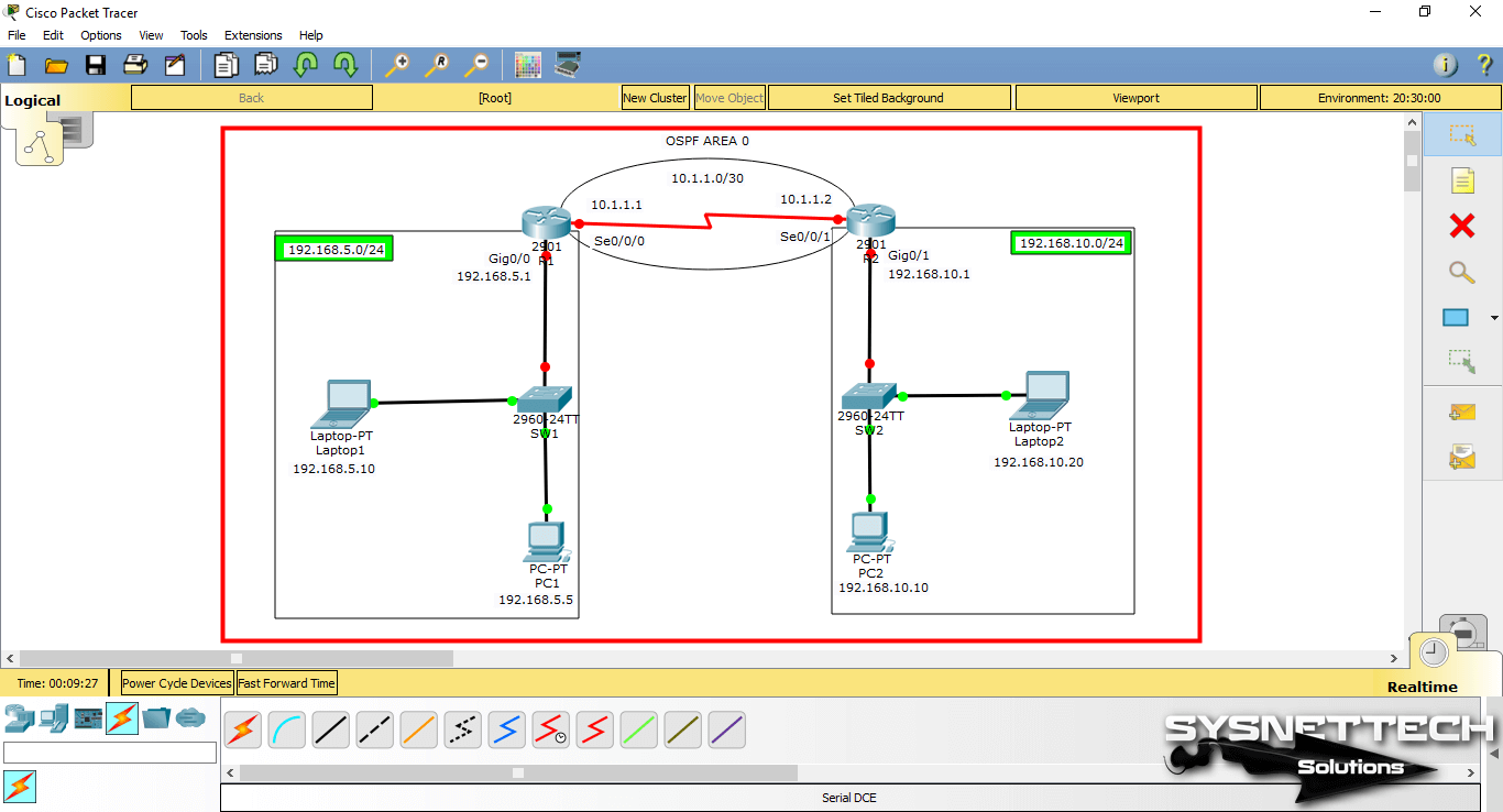
- #Packet tracer labs with ospf serial
- #Packet tracer labs with ospf full
- #Packet tracer labs with ospf verification
Verify all PCs can ping the web server and each other. Notice that the path from PC1 to 64.100.1.2 is redirected through R3. Cisco supports RFC 1253, OSPF Version 2 Management Information Base, August 1991. OSPF also allows packet authentication and uses IP multicast when sending and receiving packets.

#Packet tracer labs with ospf verification
This does not change the actual port speed, only the metric that the OSPF process on R1 will use to calculate best routes. CCNA Security labs can be downloaded for Packet Tracer versions starting from 6.1 as this version was the first to feature an ASA Firewall. This lab will discuss and demonstrate the configuration and verification of OSPF version 3.
#Packet tracer labs with ospf serial
#Packet tracer labs with ospf full
Then you will verify that full connectivity is restored for all end devices. 7.2.1 Packet Tracer Configure OSPF Advanced Features Answers Packet Tracer Configure OSPF Advanced Features (Answers Version) Answers Note: Red font color or gray highlights indicate text that appears in the instructor copy only. 2.7.3 Packet Tracer Multiarea OSPF Exploration Physical Mode (Part 3) Answers Packet Tracer OSPF Multiarea Exploration Physical Mode (Part 3) (Answers Version) Answers Note: Red font color or gray highlights indicate text that appears in the Answers copy only. You will modify the default OSPF routing configurations by changing the hello and dead timers and adjusting the bandwidth of a link. Packet Tracer 8.3.3.5 details configuration of IPv6 for OSPF, which is (of sorts) a mix of regular OSPF with different addresses and some basic IPv6 configuration commands.

In this activity, OSPF is already configured and all end devices currently have full connectivity. 10.1.3.4 Packet Tracer – Configuring OSPF Advanced Features Addressing Table Device


 0 kommentar(er)
